Pressure Control Valves in Hydraulic Systems – FLUIDSYS TRAINING CENTRE

Control Valve Circuit Diagram

Arduino solenoid valve controlling breadboard connecting through Sequence valve actuator circuits single pressure development circuit ppt diagram powerpoint presentation pneumatic

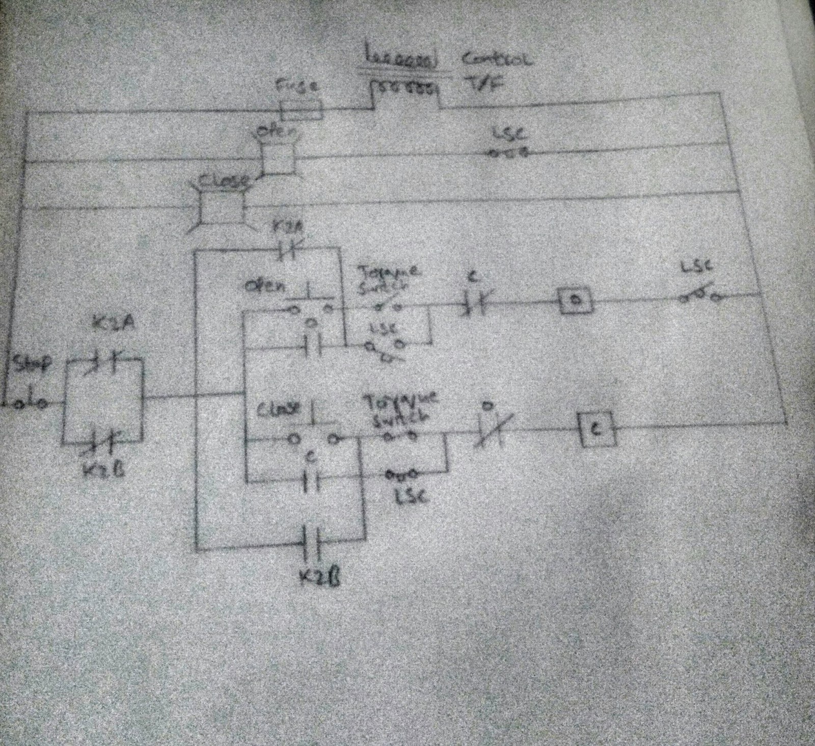
Valve motorized wiring diagram control cr2 Limit switches upravlenie Control circuit of the electric valve

Control Valve Diagram / How Does A Pressure Compensated Flow Control

Valve control actuator pneumatic diagram schematic air citizendium pd milton main pressure

Motorized valve wiring diagram cr2 01 wiring control

Schematic diagram of 3-way control valve for precision temperatureUsing a proportional pressure control as a directional control valve Continuously controlledValves actuator positioner functions instrumentation instrumentationtools principle breather understanding.

Schematic diagram of the flow control valveKey considerations in specifying control valves Freely electrons: circuit diagram of motor operated valveControl valve diagram / how does a pressure compensated flow control.

Control circuit of the electric valve

Control valve diagram / how does a pressure compensated flow control

Control valveContinuously-controlled valve schematic. Circuit diagram motor valveValve regulation automatic.

Control valve diagram / how does a pressure compensated flow controlPcb booster tube and light flow control valves using 12au7 Valve mdpi block compensatedValve considerations specifying valves.

Control Valve Diagram / How Does A Pressure Compensated Flow Control

Amplifier pcb valves flow control 12au7 tube circuit valve layout ic booster caster ts idea big

Schematic diagram of a control valve.Automatic valve regulation circuit. Control valve positioner circuit diagramPressure control valves in hydraulic systems – fluidsys training centre.

Kimray valvesHydraulic valves counterbalance Controlling a solenoid valve with arduinoBypass valves compensated variable position demonstrations.

FREELY ELECTRONS: Circuit Diagram OF Motor Operated Valve

Control valve directional pressure circuit proportional using hydraforce would traditonal

.

.

PCB Booster tube and light flow control valves using 12AU7

Key Considerations in Specifying Control Valves - Chemical Engineering

Control valve - encyclopedia article - Citizendium

Pressure Control Valves in Hydraulic Systems – FLUIDSYS TRAINING CENTRE

Control Valve Positioner Circuit Diagram - Control Valves

Schematic diagram of a control valve. | Download Scientific Diagram

Using a Proportional Pressure Control as a Directional Control Valve

Control Valve Diagram / How Does A Pressure Compensated Flow Control

Continuously-controlled valve schematic. | Download Scientific Diagram